- CYPE >
- english >
- products >
- CYPECAD MEP >
- Air conditioning


CYPECAD MEP is a program for the design of the envelope, distribution and services of the building using an integrated 3D model with the various elements of the building (dwellings, offices, hospitals, teaching centres, shops, residential, etc.). It is composed of several modules or tabs, depending on the different types of installations that can be designed.
The Air conditioning tab has been conceived to be able to completely develop an air conditioning installation (air-water or air-air systems), electric heating installation and hot water heating system with radiators, radiant floors and its boilers, all in a single program.
- Features of CYPECAD MEP's Air conditioning tab
- Import of IFC files generated by CAD/BIM programs
- Export to IFC format
- Summer and winter thermal loads
- Compact equipment selection, air-water systems
- Fan coil selection, air-water systems
- Roof-top equipment, air-air systems
- Direct expansion systems - Splits
- Variable refrigerant flow systems (VRF)
- Radiators
- Boilers
- Air conditioning ducts
- Water pipes for HVAC
- Radiant and cooling floors
- Geothermal energy harvesting systems
- Interaction between the defined precincts and group of precincts used to calculate the loads, with the description of the air conditioning installation
- Results, reports and drawings
- Specifications of the modules located in the Air conditioning tab
Features of CYPECAD MEP's Air conditioning tab
Using the Air conditioning tab of CYPECAD MEP, users can:
- Calculate the summer and winter thermal loads of any type of precinct and the air flow required to air condition the precincts that have been created.
- Select compact equipment, air-water systems (heat and cooling pumps).
- Select fan coils and air conditioning units.
- Select and design direct expansion units - Splits.
- Design air conditioning installations with compact autonomous air-air units (roof-top).
- Design air conditioning installations with variable refrigerant flow systems (VRV or VRF).
- Select and design water radiators, towel rails and electrical emitters.
- Select boilers, thermal groups and manifolds with several thermal groups.
- Analyse, check and design air handling systems. An air conditioning pre-installation analysis can be carried out for dwellings.
- Analyse, check and design water handling systems for cooling and heating.
- Design radiant and cooling floors.
- Create reports and drawings of the installation, containing the data that has been introduced and results that have been obtained.
The Air conditioning tab of CYPECAD MEP can be acquired with all the indicated calculations or with some of them depending on the user's needs. For this reason, the Air conditioning tab has several modules which allow for this option. The list of modules can be consulted in the Specifications of the modules in the Air conditioning tab section.
Import of IFC files generated by CAD/BIM programs
CYPECAD MEP can import files in IFC format generated by CAD/BIM programs such as Allplan, Archicad and Revit, thanks to the Import of CAD/BIM models module.
With this module, CYPECAD MEP can access the information of programs with BIM (Building Information Modelling) and therefore, automatically incorporate the construction elements making up the building.
CYPECAD MEP programs can import files with IFC format which have been generated by CAD/BIM programs such as Allplan, Archicad and Revit Architecture, thanks to the Import of CAD/BIM models module.
This possibility allows CYPECAD MEP’s programs to access programs with BIM (Building Information Modelling) technology and therefore, automatically incorporate the construction elements making up the building.
The exact composition of the façades and partitions (conductivity properties of each layer, position of the vapour barrier, thermal bridges, etc.) is not usually specified during the design process of the building. CYPECAD MEP incorporates an IFC format model import assistant, which allows users to automatically assign the properties of the façades, internal partitions, floor slabs, roofs, windows, etc. This way, users of the CAD/BIM program are not obliged to provide a detailed description of each element and so an effective separation between the design and technical specification is obtained for the phases of each component. Additionally, the materials are easily selected in CYPECAD MEP.
Export to IFC format
CYPECAD MEP’s programs allow for the introduced construction elements and designed building services to be exported to an IFC (Industry Foundation Classes) format file. This way, the information that has been introduced and generated in CYPECAD MEP can be read in CAD/BIM programs such as Allplan, Archicad, Revit Architecture, etc.
More information on this feature can be found in the Export to IFC format section in the CYPECAD MEP site.
Summer and winter thermal loads
The Calculation of summer thermal loads and Calculation of winter thermal loads modules carry out a complex analysis of the thermal loads of the building with the aim to obtain a correct design using transfer functions. The program considers the solar geometry and radiation at any time and any geographical location when calculating the loads. This way, a more realistic sun-air temperature is obtained.
Both the occupation and lighting loads as well as any transmission through openings are calculated in such a way, which allows for the real thermal inertia of the thermal load of the precincts to be simulated.
The program carries out the following calculations:
- Maximum cooling thermal load for all the precincts described in the job.
- Maximum simultaneous cooling thermal load for all the precinct groups described in the job. This way, the selected group can be adjusted to a maximum.
- Air flow required to air condition the precincts.
- Maximum heating thermal load.
- Maximum simultaneous heating thermal load.
The program designs the installation by distributing the thermal load amongst all the emitters in a precinct (fan coils, air conditioners, radiators, towel rails, heat accumulators and convectors). This way, if any data used to calculate the thermal loads is modified (different orientation, changes in the climatic conditions, partitions properties, etc.), the program automatically redesigns the entire installation, avoiding incompatibilities and saving time, which is very beneficial for the user.
If users choose not import the construction elements using an IFC file that has been generated by a CAD/BIM program, these can be defined manually, with or without the help of drawing files with DXF, DWG, JPEG, JPG, BMP, WMF, EMF or PCX format.
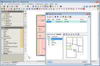
CYPECAD MEP's tabs (Fire and Air conditioning) share the same introduction data with regards to the construction elements (floor slabs, façades, partitions, roofs, openings...). This way, once the data has been introduced in one of the tabs, it does not have to be redefined again.
This introduction tool, makes CYPECAD MEP stand out from the building services programs available in today's market, due to the speed with which the data, required to obtain the summer and winter loads, can be introduced.
The reason for this speed is due to the construction element introduction and definition of the precincts being two separate processes.
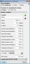
Users define the climatic conditions (altitude, latitude, longitude, summer temperatures, winter temperatures, humidity…) of the location of the job and the program allows for this data to be saved in a library to then be available for future jobs.
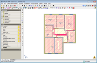
Users have to introduce all the façades, partitions, openings, floor slabs and roofs of the building, with no regard as to which precinct each one corresponds to. This work can be carried out comfortably using a template with DXF, DWG, JPEG, JPG, BMP, WMF, EMF or PCX format; therefore, there is no need to measure the façades, partitions or openings. The advantage of being able to import templates with all the formats indicated above, is that that even a scanned drawing containing the building services and construction elements can be used as a template, greatly helping with data introduction.
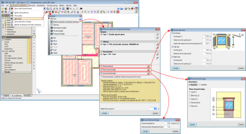
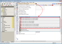
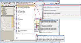
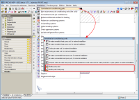
Thermal bridges included in the thermal envelope of a building are automatically identified when the analysis of the construction elements that have been introduced is carried out from the Air conditioning tab (Results > Analyse). The program allows users to define the thermal bridges manually or using the Numerical analysis of linear thermal bridges module (which provides a more precise analysis of the Linear transmittance of the thermal bridges).
More information on the webpage Numerical analysis of linear thermal bridges. ![]()
Plane thermal bridges can be defined in a simplified manner (by indicating the total width of the thermal bridge at the opening and thermal transmission coefficient U) or in a detailed manner (by activating the components of the opening – lintel, blind box, jambs, window sill and niche, and defining them as is done with the partitions or by indicating the thermal transmission coefficient, U, of each element).
Overhanging shading devices can be defined on windows. The program also contemplates how much the windows are setback with respect to the external face of the façade to take into account the shadow that is produced.
Users do not have to provide the data of the windows each time one is introduced. The program allows for several types of windows to be defined with all their properties and users just have to select the type when they are going to be introduced. If any of their properties are modified, the correction will affect all the windows of the same type included in the job.
Data of the Windows and construction elements can be saved in user libraries for use in future jobs.
The orientation is defined once, and the program automatically assigns all the corresponding orientation to the external elements.
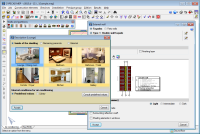
Once the elements have been established, the precincts are then introduced using a library which can be modified as the user wishes.
This way, all this data only has to be introduced once and so, ensures no further introduction errors are made, as the library guarantees the same data will be present in other jobs.
The data incorporated in each precinct is the following:
- Internal conditions
- Occupancy
- Lighting
- Ventilation
- Equipment or other loads
The precinct is defined by indicating the point where it is to be placed, and the program automatically assigns the partitions surrounding it.
For installations providing heating and cooling, the program allows for precincts which only require heating to be introduced (bathrooms and toilets), and includes these precincts for the heating design and not for the cooling design.
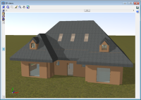
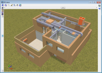
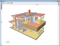
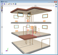
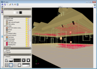
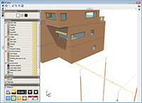
A 3D view of the building can be obtained at any moment, allowing users to locate possible errors in the introduction of the construction elements.
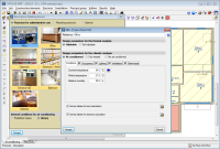
Compact equipment selection, air-water systems
This module allows users to easily select the air conditioning equipment, based on air-water systems (heat and cooling pumps).
The equipment is placed at its real position on the floor plan. They are displayed with their dimensions and include maintenance space; allowing the user to ensure that the space required for the correct maintenance of the installation is present.
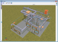
The pipe connections with the equipment are taken at their 3D position, and so the real length of the pipe is considered in the design. An integrated 3D view of the equipment with its real dimensions is also provided.
Fan coil selection, air-water systems
This module allows users to easily select the fan coils and air conditioners for the air conditioning installation.
The fan coils are placed at their real position depending on the type: (ceiling, wall, dropped ceiling, floor, etc., taking into account their dimensions. The program automatically considers the interaction it has with the various construction elements that are implied (wall thickness, floor slab depth, dropped ceiling arrangement, elevation changes, etc.) to carry out a real positioning of the fan coil.
Pipe and duct connections are placed at their real positions, and include, in the case of ducts, the outlet dimensions (fan coils and air conditioning equipment) with duct distribution) and air inlet dimensions. This allows for an exact design of the pipe lengths and parts of the ducts, as well as observing the integrated fan coils in the real 3D view of the installation.
The program allows for the heat or cooling pump systems to be combined with thermal groups or boilers to feed the fan coils and air conditioning equipment.
Roof-top equipment, air-air systems
This module allows for the design of air conditioning installations with compact air-air autonomous units (roof-top). The roof-top equipment is for use in tertiary and industrial buildings, where its main advantage is the absence of water and cooling pipes in the precincts. Therefore, the installation is easier to assemble and the time required for its execution is reduced.
Additionally, using this module, users can design air conditioning installations with units that include free-cooling and heat recovery.
Direct expansion systems - Splits
The Direct expansion systems – Splits module has been conceived to design an air-air installation with 1x1 and multi-split systems.
This module allows for the following elements to be introduced in the air conditioning installation:
- Air conditioning set with internal wall unit, air-air 1x1 split system
- Air conditioning set with internal unit with tubular duct distribution, air-air 1x1 split system
- Air conditioning set with internal cassette unit, air-air 1x1 split system
- Air conditioning set with internal roof unit with direct discharge, air-air 1x1 split system
- Air conditioning set with internal unit with rectangular duct distribution, air-air 1x1 split system
- Internal wall air conditioning unit, air-air multi-split system
- Internal air conditioning unit with tubular duct distribution, air-air multi-split system
- Internal air conditioning cassette unit, air-air multi-split system
- Internal roof air conditioning unit with direct discharge, air-air multi-split system
- Internal air conditioning unit with rectangular duct distribution, air-air multi-split system
- External air conditioning unit, air-air multi-split system
- Cooling line with double isolated pipe
For the Direct expansion systems – Splits – module to be able to design an air-air air conditining installation, users must have the Calculation of thermal loads and Air conditioning ducts modules (this last module is required if equipement with distribution using ducts is introduced).
Variable refrigerant flow systems (VRF)
The Variable refrigerant flow systems (VRF) module is integrated within the Air conditioning tab of CYPECAD MEP and has been conceived to design an air conditioning installation with variable refrigerant flow systems.
This option opens a dialogue box in which users can select the following air conditioning elements to be introduced:
- External air conditioning unit.
- Internal air conditioning unit with distribution using a rectangular duct
- Internal cassette air conditioning unit.
- Internal cassette air conditioning unit, visible.
- Cassette connection box, visible.
- Internal roof air conditioning unit, with direct discharge.
- Air curtain.
- Internal wall air conditioning unit.
- Internal floor air conditioning unit.
- Manifold.
- Branch joint.
- Cooling line, horizontal.
- Cooling line, vertical.
Users introduce the internal air conditiong units, the necessary connection elements (ducts, cooling lines, manifolds) and position of the external unit. The program checks that the internal units that have been provided cover the thermal loads that have been calculated and designs the external unit or units so they can supply the internal installation that has been introduced, considering a Maximum capacity percentage (whose default value is set to 115%, but can be modified by users).
For the Variable refrigerant flow systems (VRF) module to be able to design an air conditioning installation, users must, besides this module, have the Calculation of thermal loads and Air conditioning ducts modules (this last module is required if equipement with distribution using ducts is introduced).
Radiators
The Radiators module allows users to introduce water radiators, steel plate panels, towel rails and electrical emitters (heat accumulators, convectors and electric radiators).
Radiators are designed automatically using the thermal loads calculated by the Calculation of winter thermal loads module. Users select the maximum width the emitter can have by marking two points on plan. The program then introduces the number of elements that are required and emits a warning if the width is exceeded. The number of elements of a radiator can also be established. This way, the radiator design in the precincts can be adapted to users’ needs. The number of elements of a series of radiators within the same precinct can be established and the program will calculate the elements required in the remaining precincts. If the number of elements of the all the radiators of a precinct is established, the program will emit a warning if more elements are required for a radiator. This warning does not prevent the installation from being designed.
In the case of towel rails, the program directly calculates the emitted power.
The program designs the installation by distributing the thermal load amongst all the emitters of the precinct. This way, if there are any changes in the data for the thermal load calculation (different orientation, changes in climatic conditions or partition conditions, etc.), the program will automatically redesign the entire installation, avoiding incompatibilities and saving time.
Boilers
The Boilers module offers users the possibility to introduce individual boilers and thermal groups (gas, gasoil or electric boilers) for heating, or heating and hot water. Manifolds with several thermal sets can also be included, multiplying the maximum power of the installation.
The boilers and thermal sets introduced by users are checked with the program in accordance with the calculations carried out by this module. As the program displays the real dimensions of the equipment at all times, users can change the boiler or thermal set and check if the new dimensions are compatible with the available space. For mixed boiler and thermal sets, the program takes into account the hot water requirements.
A fundamental aspect of the heating installation is that if any data used to calculate the thermal loads is modified (different orientation, changes in the climatic conditions, partitions properties, etc.), the program automatically redesigns the entire installation, avoiding incompatibilities and saving time, which is very beneficial for the user.
Air conditioning ducts
All the elements required for the air installation are introduced in the program as well as the design and analysis options that will affect the results.
Ducts can be rectangular, rigid circular or flexible circular. This last type of ducts allow for installations incorporating plenum diffusers.
A wide range of elements for the installation are available: diffusers (with or without plenum), supply air grilles, nozzles, return air grilles (with or without plenum), exhaust and intake air grilles, linear centrifugal ventilators and air-air static heat recoverers.
The program designs the grilles in accordance with the aesthetics of the precinct.
The analysis, check and design of the air conditioning ducts is carried out using the static regain method and constant pressure loss method.
The air conditioning pre-installation in dwellings can be obtained by designing the requirements of the equipment together with the entire air conditioning installation (ducts, diffusers and grilles) depending on the thermal loads. The dimensions of the dropped ceiling and aesthetics of the precinct are considered in the design. For example, in the case of a discharge and a return grille, the program selects a single size for both. The overpressure the precinct is to have when discharging and with air return is also considered. For the program to design the air conditioning pre-installation, users must have the Calculation of thermal loads and Air conditioning ducts modules.
Water pipes for HVAC
Using this module, users can analyse, check and design water pipes for air conditioning.
Features of this module include:
- Possibility to introduce several pipes simultaneously along a singe polygon.
- Two-pipe system with direct and inverted return.
- Monopipe system.
- Connections to equipment considering the real position of the connection point.
- Integration in the 3D view of the installation.
- Introduction of discharge and return manifolds.
The program has tools available to introduce and define all the elements required for the pipe installation.
By introducing discharge and return manifolds for the water circuit, users can introduce equipment that will work simultaneously in the same circuit; allowing for the designed installation to be of any size. The program checks whether a hydraulic set is required for the installation, as well as designing the primary and secondary circuits.
Radiant and cooling floors
Using the Radiant and cooling floors module, integrated in the Air conditioning tab of CYPECAD MEP, users can design radiant floor installation in accordance with EN 1264.
The program designs the radiants floors in such a way, so that it is compatible with other systems such as radiators, towel rails, electrical emitters, fan coils etc.
Air conditioning systems composed of radiant and cooling floors can be implemented in single or collective installations by connecting them to production elements such as electric boilers, gasoil boilers, gas boilers, gasoil thermal sets, gas thermal sets and central heating units (heat and cooling pumps).
More information can be found on the Radiant and cooling floor webpage.
Geothermal energy harvesting systems
The module: Geothermal energy harvesting systems, integrated in the Air Conditioning tab of CYPECAD MEP, has been conceived to design geothermal energy harvesting systems.
Geothermal heat pump systems are geothermal systems with low enthalpy which use a heat pump and an energy harvesting system in the ground to utilise the temperature of the ground.
The Geothermal energy harvesting systems module of CYPECAD MEP allows users to design the geothermal heat exchanger that is required for the installation to operate correctly, based on the selection of a geothermal heat pump and the definition of the energy requirements it must cover.
More information can be found on the Geothermal energy harvesting systems webpage.
Interaction between the defined precincts and group of precincts used to calculate the loads, with the description of the air conditioning installation
CYPECAD MEP integrates the data and results of the thermal loads calculated using the designed installation. The program designs the installation by distributing the thermal load amongst all the emitters included in the precinct (fan coils, air conditioners, radiators, towel rails, heat accumulators and convectors). This way, if any data used to calculate the thermal loads is modified (different orientation, changes in the climatic conditions, partitions properties, etc.), the program automatically redesigns the entire installation, avoiding incompatibilities and saving time, which is very beneficial for the user.
Results, reports and drawings
Complete data and result reports can be obtained in the Air conditioning tab of CYPECAD MEP. After seeing the preliminary view, these can be printed directly via a printer or exported as a text (TXT) file, HTML, PDF or RTF. The generated reports are as follows:
- Building elevation configuration
- Description of all the building precincts
- Tables of the maximum thermal loads of each precinct
- Tables of the contribution of each precinct to the simultaneous thermal load of each precinct group.
- Daily evolution of the maximum thermal load of each building.
- Annual evolution of the maximum thermal load of each precinct and of the precinct group which it belongs to.
- Results of the installation design
The program has a powerful drawing generation tool with which users will not have to access CAD to generate the drawings. Construction elements from templates in DXF, DWG, JPEG, JPG, BMP, WMF or PCX format can be included in the drawings. These templates can also be used to help with data introduction, as was explained previously in Summer and winter thermal loads (Data entry).
Specifications of the modules located in the Air conditioning tab
Several modules are available for use in the Air conditioning tab. Users can acquire all the modules or combine them in different ways. These modules are:
- Calculation of winter thermal loads
- Calculation of summer thermal loads
- Compact equipment selection. Air-water systems
- Fan coil selection. Air-water systems
- Roof-top equipment. Air-air systems
- Direct expansion systems – Splits
- Variable Refrigerant Flow Systems (VRF)
- Radiators
- Boilers
- Air conditioning ducts
- Water pipes for HVAC
- Radiant and cooling floors
Please contact us for advice on which module combination best suits your needs.
The air conditioning pre-installation design can be carried out if the user license contains permits to use the Calculation of thermal loads and Air conditioning ducts modules.
The Boilers module requires users to have acquired the Calculation of winter thermal loads module to be able to design water radiators, towel rails and electrical emitters.
The Boilers module requires users to have acquired the Calculation of winter thermal loads module and Water pipes for HVAC module to be able to design the boilers.
Even though the program contains several modules, they are all combined in a single program so users do not have to use other IT tools, which makes the program unique compared to all those available in the market.
Tel. USA (+1) 202 569 8902 // UK (+44) 20 3608 1448 // Spain (+34) 965 922 550 - Fax (+34) 965 124 950