
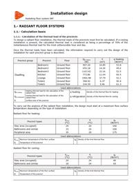
 Using the Radiant and cooling floor module, integrated in the Air Conditioning tab of CYPECAD MEP, users can design radiant floor installations in accordance with the method described in the EN 1264 code.
The program allows for the design of the radiant floor to take into account other heating elements such as radiators, towel rails, electric emitters, fan coils etc.
The radiant and cooling floor system can be implemented in individual and collective installations, connecting it to heat production elements such as electric boilers, diesel boilers, gas boilers, diesel thermal boilers, and central air conditioning units (heat and cooling pumps).
Data introduction
 For the Cooling and radiant floors module to be able to design an installation, the construction elements and precincts of the building must first be defined, so that the program can calculate the summer and winter thermal loads. This data is also used by other building services designed by CYPECAD MEP. Thanks to the connectivity of the program, users designing the installations of the building can define this data beforehand.
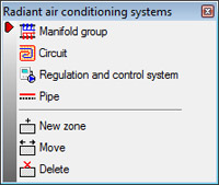
The elements which are exclusive to the radiating floor installation, and which users must select and define are the Manifold group and Radiating floor circuits, and, if the installation requires it, the Regulation and control system (the program checks whether this element is required in the installation).
Users define the properties of the radiant floor system: the number of circuits (between 2 and 12); the manufacturer of the system; use for heating and cooling, or only heating; the properties of the manifold; the type of pipe-holding panel; whether or not levelling mortar is to be used and, if so, its thickness.
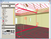
When the manifold group is positioned in the installation, users can see the real size of the box in which it is contained. This way, users can perform a visual check that it does not interfere with any other construction element of the installation.
The pipes connecting the manifold group to the production set should also be placed.
The radiant floor circuits are introduced in two steps:
- The part of the circuit situated inside the precinct which is to be conditioned
- The connection between the manifold group and part situated in the precinct
 Therefore users can first of all introduce the circuits of each of the precincts and later join each of them to the manifold group; making the data introduction process easier.
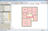
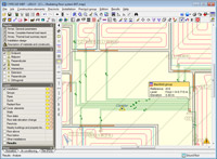
When the part of the circuit situated inside a precinct is introduced, the program carries out a quick design and instantaneously draws the shape of the circuit (double- coil or spiral) and the spacing between the pipes, bearing in mind the geometry of the precinct where it is located. Users obtain an on-screen view of the circuit whilst moving the cursor around the limits of the precincts, and all that must be done is select the entry point of the circuit.
If the installation is designed simultaneously for a radiant floor and cooling floor, the distance between the pipes is kept constant in all the precincts of the building so to avoid condensation problems with an approximate spacing of 15cm, which may vary depending on the manufacturer.
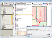
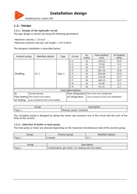
Once the installation has been designed, each radiant floor circuit can be edited (Installation > Edit) so to modify the following properties: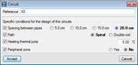
- Spacing between pipes
Users can choose a distance of 5, 10, 15 or 20 cm.
- The path of the installation
The circuit can consist of a double coil or spiral arrangement.
- The cooling thermal jump
- The heating thermal jump
- Consideration of the peripheral area
 The program detects automatically if a circuit can be treated as a peripheral area (surfaces whose width is less than one metre next to the limits of the precinct) to allow for a greater surface temperature and, hence provide more heat. Nonetheless, and having designed the installation, users can decide if a radiant circuit is in a peripheral area or stay area.
If the installation is designed simultaneously to be a radiant and cooling floor, users can modify the spacing between the pipes that has been provided automatically by the program (recommended by the manufacturer); after the analysis, a warning sign will appear next to the circuits that have been modified to remind user that they have changed the spacing of the pipes.
The path of the circuit connecting the part situated in the precinct to the manifold group, is defined by users.
 Users can define several areas within a precinct, and so be able to introduce several circuits in a precinct. This is useful when there are large surfaces requiring a radiant floor installation.
Areas containing more than one precinct can also be defined and so, be able to introduce the same circuit in several precincts. This way, precincts separated by virtual partitions can be designed with the same circuit.
Regulation and control system of the installation
A regulation and control system can be defined if required by the installation. The program controls the need to introduce a regulation and control system in single hot water production installations. This system is required for:
- Radiant installations with production of hot water at high temperatures to control the mix when reaching the manifolds (by re-circulating or acting upon the different elements of the installation).
- In radiant and cooling floor systems to avoid condensation problems (by controlling the humidity).
Design carried out by the program
When users introduce the circuit located in a precinct, the program initially designs the shape of the radiant circuit (double-coil or spiral) and the path of the pipes, bearing in mind the geometry of the precinct in which it is placed.
When the installation is analysed, the program designs all the circuits depending on their thermal load, the geometry of the precinct and the composition of the floor, and so obtaining the definitive shape of each circuit and spacing of the pipes, and the flow in accordance with that described in the EN 1264 code.
Documents generated by the program

Once the radiant floor installation has been analysed, users can obtain justification documents, which include the following sections:
- Calculation basis
- Calculation of the thermal load of the precincts
- Location of the manifolds
- Design of the circuits. Calculation of the lengths
- Calculation of the flow temperature of the water
- Calculation of the water flow of the circuits
- Design
- Design of the hydraulic circuit
- Selection of boiler or heat pump
- Annex A: Analysis annex
Besides the document which is exclusive to the radiant floor installation, justification documents and reports related to the rest of the designed air conditioning and heating installation can be obtained, depending on the user license permits. These are listed in the Results, reports and drawings section of the Air conditioning page.
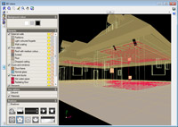
The program generates the drawings of all the floors of the building in several formats (including DXF and DWG), which include, as well as all the construction elements, all the elements of the air conditioning and heating installation.
Required and recommended Air conditioning modules for the design of a radiant floor installation
The Radiant and cooling floors module can design the installation for heating only or for heating and cooling. For the program to design the radiant floor installation, and depending on the calculations users wish to carry out, the following modules are required, recommended or optional:
- Radiant floor design (only heating)
- The following modules are required:
- Calculation of thermal loads
- Radiant and cooling floors
- Water pipes for HVAC
- Boilers or Compact equipment selection
- It is recommended the following modules also be acquired:
- Radiators
- Connection with the Price Generator (Allows for the installation to be accounted for in the bill of quantities).
- The following modules are optional:
- Radiant and cooling floor design (heating and cooling)
- The following modules are required:
- Calculation of thermal loads
- Calculation of summer thermal loads
- Radiant and cooling floors
- Water pipes for HVAC
- Compact equipment selection
- Fan coil selection
- It is recommended the following module also be acquired:
- Connection with the Price Generator (Allows for the installation to be accounted for in the bill of quantities).
- The following modules are optional:
Tel. USA (+1) 202 569 8902 // UK (+44) 20 3608 1448 // Spain (+34) 965 922 550 - Fax (+34) 965 124 950